Biosensing
Biosensing and Networked Performance Workshop at ISEA 2011 in Istanbul led by Anna Dumitriu and Tom Keene with Alex May. Venue: ISEA 2011 Istanbul 15th and 16th September 9am-1pm 2011. Caryl Mann Composed the startup music for the Galvanic skin response device.
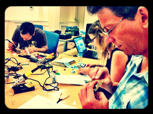
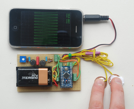
In this two-day workshop participants built and calibrated their own iPhone compatible/connectable Galvanic Skin Response Sensors (GSR) to record subtle changes in their emotional arousal. Participants will also collaborated to develop a networked performance intervention that engaged with the social benefits and ethical implications of disclosing such personal information as arousal levels within the public realm. Participants learnt to solder and connect their own GSR sensors, connect them to their iPhones and share their sensor data online. There was a discussion of the implications of this technology and the increasing issues of privacy as pervasive computing technology is increasingly able to record and reveal personal details.
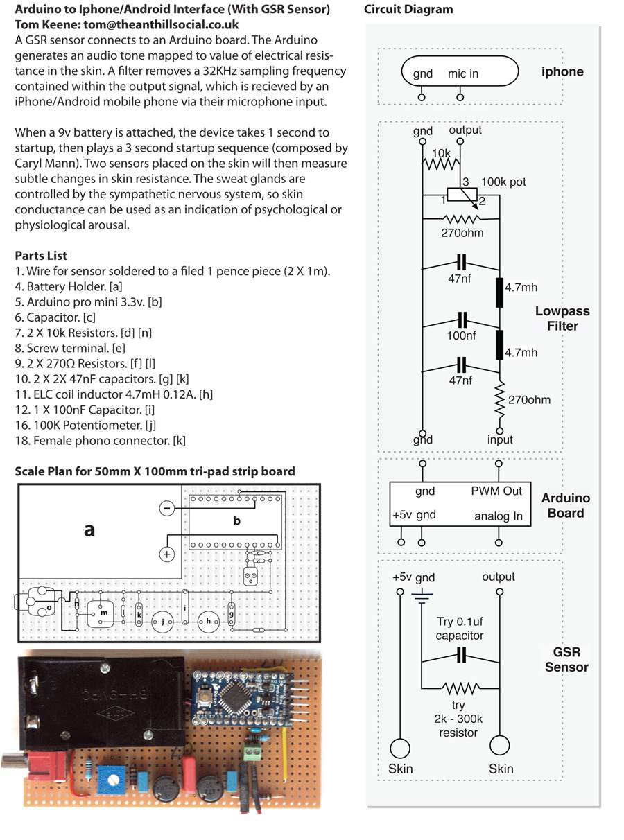
Build sheet
Arduino Code
The script was forked from DDS Sinewave Generator code developed by LabIII, The Laboratory for Experimental Computer Science at the Academy of Media Arts Cologne.
// SMOOTHING
const int numReadings = 10;
int readings[numReadings];      // the readings from the analog input
int index = 0;                  // the index of the current reading
int total = 0;                  // the running total
int average = 0;                // the average
int inputPin = A0;              // this pin this sensor is attached to
void initialiseSmooth(){
  for (int thisReading = 0; thisReading < numReadings; thisReading++) // initialize all the readings to 0:
    readings[thisReading] = 0;
}
int readSmooth(){
  total= total - readings[index];         // subtract the last reading
  readings[index] = analogRead(inputPin); // read from the sensor
  total= total + readings[index];         // add the reading to the total
  index = index + 1;                      // advance to the next position in the array:
  if (index >= numReadings)              // if we're at the end of the array...
    index = 0;                           // ...wrap around to the beginning
  average = total / numReadings;         // calculate the average
  return  average;
}

void setup()
{
   // Smoothing setup
   initialiseSmooth();
   // Wavetable setup
   o1.phase = 0;
   o1.phase_increment = 0 ;
   o1.amplitude_increment = 0;
   o1.frequency_increment = 0;
   o1.framecounter =0;
   o1.amplitude = 0; // zero amplitude
   initializeTimer();
   // startupsounds
   carylMannComposition();
}

void loop() {
    // Read the analog input
    dfreq = readSmooth();          // read analog pin to adjust output frequency from 0..1023 Hz
    dfreq = 1023-dfreq;            // inverse the reading so tone sounds higher the less resistance there is
    o1.phase_increment = phaseinc(dfreq);
}

// Startup sequence
// (Music composed by Caryl Mann: carylharp@gmail.com)
// TODO: Should really create a lookup table for this...
void carylMannComposition()
{
  // Startup sequence (Convert 'midi ticks' to millisencons:  60000 / (BPM * PPQ))
  // At 100bmp 1 tick = 2.36 milliseconds
  o1.amplitude = 255*256; // full amplitude
  o1.phase_increment = phaseinc(440.00); // A4 - ticks
  delay(90);
    o1.phase_increment = phaseinc(174.61); // F3 - ticks
  delay(90);
    o1.phase_increment = phaseinc(523.25); // C5 - ticks
  delay(90);
    o1.phase_increment = phaseinc(349.23); // F4 - ticks
  delay(90);
    o1.phase_increment = phaseinc(659.26); // E5
  delay(90);
    o1.phase_increment = phaseinc(698.46); // F5
  delay(90);
    o1.amplitude = 0;
  delay(350);
    o1.amplitude = 255*256; // full amplitude
    o1.phase_increment = phaseinc(164.81); // E3
  delay(90);
    o1.phase_increment = phaseinc(293.66); // D4
  delay(111);
    o1.amplitude = 0;
  delay(111);
    o1.amplitude = 255*256; // full amplitude
    o1.phase_increment = phaseinc(466.16); // A#4
  delay(111);
    o1.phase_increment = phaseinc(739.99); // F#5
  delay(100);
    o1.amplitude = 0;
  delay(600);
  o1.amplitude = 255*256; // full amplitude
    o1.phase_increment = phaseinc(1108.73); // C#6
  delay(95);
    o1.phase_increment = phaseinc(369.99); // F#4
  delay(95);
    o1.phase_increment = phaseinc(466.16); // A#4
  delay(95);
    o1.phase_increment = phaseinc(233.08); // A#3
  delay(254);
    o1.amplitude = 0;
  delay(100);
    o1.amplitude = 255*256; // full amplitude
    o1.phase_increment = phaseinc(698.46); // F5
  delay(300);
    o1.phase_increment = phaseinc(174.61); // F3
  delay(300);
    o1.amplitude = 0;
  delay(1000);
    o1.amplitude = 0; // full amplitude
}

// ATMEGA TABLE-BASED DIGITAL OSCILLATOR
// using "DDS" with 32-bit phase register to illustrate efficient
// accurate frequency.
// 20-bits is on the edge of people pitch perception
// 24-bits has been the usual resolution employed.
// so we use 32-bits in C, i.e. long.
//
// smoothly interpolates frequency and amplitudes illustrating
// lock-free approach to synchronizing foreground process  control and background (interrupt)
// sound synthesis

// On old ATmega8 boards, output is on pin 11
// For modern ATmega168 boards, output is on pin 3

// copyright 2009. Adrian Freed. All Rights Reserved.
// Use this as you will but include attribution in derivative works.
// tested on the Arduino Mega

#include <avr/io.h>
#include <avr/interrupt.h>
#include <avr/pgmspace.h>
double dfreq;
const unsigned int LUTsize = 1<<8; // Look Up Table size: has to be power of 2 so that the modulo LUTsize
                                   // can be done by picking bits from the phase avoiding arithmetic
int8_t sintable[LUTsize] PROGMEM = { // already biased with +127
  127,130,133,136,139,143,146,149,152,155,158,161,164,167,170,173,
  176,179,182,184,187,190,193,195,198,200,203,205,208,210,213,215,
  217,219,221,224,226,228,229,231,233,235,236,238,239,241,242,244,
  245,246,247,248,249,250,251,251,252,253,253,254,254,254,254,254,
  255,254,254,254,254,254,253,253,252,251,251,250,249,248,247,246,
  245,244,242,241,239,238,236,235,233,231,229,228,226,224,221,219,
  217,215,213,210,208,205,203,200,198,195,193,190,187,184,182,179,
  176,173,170,167,164,161,158,155,152,149,146,143,139,136,133,130,
  127,124,121,118,115,111,108,105,102,99,96,93,90,87,84,81,
  78,75,72,70,67,64,61,59,56,54,51,49,46,44,41,39,
  37,35,33,30,28,26,25,23,21,19,18,16,15,13,12,10,
  9,8,7,6,5,4,3,3,2,1,1,0,0,0,0,0,
  0,0,0,0,0,0,1,1,2,3,3,4,5,6,7,8,
  9,10,12,13,15,16,18,19,21,23,25,26,28,30,33,35,
  37,39,41,44,46,49,51,54,56,59,61,64,67,70,72,75,
  78,81,84,87,90,93,96,99,102,105,108,111,115,118,121,124
};
int8_t triangletable[LUTsize] PROGMEM = {
  0x00,0x02,0x04,0x06,0x08,0x0a,0x0c,0x0e,0x10,0x12,0x14,0x16,0x18,0x1a,0x1c,0x1e,
  0x20,0x22,0x24,0x26,0x28,0x2a,0x2c,0x2e,0x30,0x32,0x34,0x36,0x38,0x3a,0x3c,0x3e,
  0x40,0x42,0x44,0x46,0x48,0x4a,0x4c,0x4e,0x50,0x52,0x54,0x56,0x58,0x5a,0x5c,0x5e,
  0x60,0x62,0x64,0x66,0x68,0x6a,0x6c,0x6e,0x70,0x72,0x74,0x76,0x78,0x7a,0x7c,0x7e,
  0x80,0x82,0x84,0x86,0x88,0x8a,0x8c,0x8e,0x90,0x92,0x94,0x96,0x98,0x9a,0x9c,0x9e,
  0xa0,0xa2,0xa4,0xa6,0xa8,0xaa,0xac,0xae,0xb0,0xb2,0xb4,0xb6,0xb8,0xba,0xbc,0xbe,
  0xc0,0xc2,0xc4,0xc6,0xc8,0xca,0xcc,0xce,0xd0,0xd2,0xd4,0xd6,0xd8,0xda,0xdc,0xde,
  0xe0,0xe2,0xe4,0xe6,0xe8,0xea,0xec,0xee,0xf0,0xf2,0xf4,0xf6,0xf8,0xfa,0xfc,0xfe,
  0xff,0xfd,0xfb,0xf9,0xf7,0xf5,0xf3,0xf1,0xef,0xed,0xeb,0xe9,0xe7,0xe5,0xe3,0xe1,
  0xdf,0xdd,0xdb,0xd9,0xd7,0xd5,0xd3,0xd1,0xcf,0xcd,0xcb,0xc9,0xc7,0xc5,0xc3,0xc1,
  0xbf,0xbd,0xbb,0xb9,0xb7,0xb5,0xb3,0xb1,0xaf,0xad,0xab,0xa9,0xa7,0xa5,0xa3,0xa1,
  0x9f,0x9d,0x9b,0x99,0x97,0x95,0x93,0x91,0x8f,0x8d,0x8b,0x89,0x87,0x85,0x83,0x81,
  0x7f,0x7d,0x7b,0x79,0x77,0x75,0x73,0x71,0x6f,0x6d,0x6b,0x69,0x67,0x65,0x63,0x61,
  0x5f,0x5d,0x5b,0x59,0x57,0x55,0x53,0x51,0x4f,0x4d,0x4b,0x49,0x47,0x45,0x43,0x41,
  0x3f,0x3d,0x3b,0x39,0x37,0x35,0x33,0x31,0x2f,0x2d,0x2b,0x29,0x27,0x25,0x23,0x21,
  0x1f,0x1d,0x1b,0x19,0x17,0x15,0x13,0x11,0x0f,0x0d,0x0b,0x09,0x07,0x05,0x03,0x01,
};
const int timerPrescale=1<<9;
struct oscillator
{
    uint32_t phase;
    int32_t phase_increment;
    int32_t frequency_increment;
    int16_t amplitude;
    int16_t amplitude_increment;
    uint32_t framecounter;
} o1;
const int fractionalbits = 16; // 16 bits fractional phase
// compute a phase increment from a frequency
unsigned long phaseinc(float frequency_in_Hz)
{
   return LUTsize *(1l<<fractionalbits)* frequency_in_Hz/(F_CPU/timerPrescale);
}
// The above requires floating point and is robust for a wide range of parameters
// If we constrain the parameters and take care we can go much
// faster with integer arithmetic
// We control the calculation order to avoid overflow or resolution loss
 //
 // we chose "predivide" so that (pow(2,predivide) divides F_CPU,so 4MHz (1.7v), 8Mhz, 12Mhz (3.3v) and 16Mhz 20Mhz all work
 // AND note that "frequency_in_Hz" is not too large. We only have about 16Khz bandwidth to play with on arduino timers anyway
const int predivide = 8;
unsigned long phaseinc_from_fractional_frequency(unsigned long frequency_in_Hz_times_256)
{
    return (1l<<(fractionalbits-predivide))* ((LUTsize*(timerPrescale/(1<<predivide))*frequency_in_Hz_times_256)/(F_CPU/(1<<predivide)));
}

// tabulate phaseincrements correspondending to equaltemperament and midi note numbers (semitones)
#define MIDITOPH
#ifdef MIDITOPH
#define mtoph(x) ( phaseinc(8.1757989156* pow(2.0, x /12.0) ))
unsigned long midinotetophaseinc[128]=
{
  mtoph(0), mtoph(1), mtoph(2),mtoph(3), mtoph(4), mtoph(5), mtoph(6), mtoph(7),
  mtoph(8),mtoph(9), mtoph(10), mtoph(11), mtoph(12), mtoph(13), mtoph(14), mtoph(15),
   mtoph(16), mtoph(17), mtoph(18), mtoph(19), mtoph(20), mtoph(21), mtoph(22), mtoph(23),
  mtoph(24), mtoph(25), mtoph(26), mtoph(27), mtoph(28), mtoph(29), mtoph(30), mtoph(31),
   mtoph(32), mtoph(33), mtoph(34), mtoph(35), mtoph(36), mtoph(37), mtoph(38), mtoph(39),
  mtoph(40), mtoph(41), mtoph(42), mtoph(43), mtoph(44), mtoph(45), mtoph(46), mtoph(47),
   mtoph(48), mtoph(49), mtoph(50), mtoph(51), mtoph(52), mtoph(53), mtoph(54), mtoph(55),
  mtoph(56), mtoph(57), mtoph(58), mtoph(59), mtoph(60), mtoph(61), mtoph(62), mtoph(63),
  mtoph(64), mtoph(65), mtoph(66), mtoph(67), mtoph(68), mtoph(69), mtoph(70), mtoph(71),
  mtoph(72), mtoph(73), mtoph(74), mtoph(75), mtoph(76), mtoph(77), mtoph(78), mtoph(79),
   mtoph(80), mtoph(81), mtoph(82), mtoph(83), mtoph(84), mtoph(85), mtoph(86), mtoph(87),
  mtoph(88), mtoph(89), mtoph(90), mtoph(91), mtoph(92), mtoph(93), mtoph(94), mtoph(95),
   mtoph(96),mtoph(97), mtoph(98), mtoph(99), mtoph(100), mtoph(101), mtoph(102), mtoph(103),
  mtoph(104),mtoph(105), mtoph(106), mtoph(107), mtoph(108), mtoph(109), mtoph(110), mtoph(111),
   mtoph(112),mtoph(113), mtoph(114), mtoph(115), mtoph(116), mtoph(117), mtoph(118), mtoph(119),
  mtoph(120), mtoph(121), mtoph(122), mtoph(123), mtoph(124), mtoph(125), mtoph(126), mtoph(127)
 };
#undef mtoph
#endif


// Timer setup constants
#if defined(__AVR_ATmega8__)

// On old ATmega8 boards, output is on pin 11
#define PWM_PIN       11
#define PWM_VALUE_DESTINATION     OCR2
#define PWM_INTERRUPT TIMER2_OVF_vect
#elif defined(__AVR_ATmega1280__)

#define PWM_PIN       3
#define PWM_VALUE_DESTINATION     OCR3C
#define PWM_INTERRUPT TIMER3_OVF_vect
#else

// For modern ATmega168 boards, output is on pin 3
#define PWM_PIN       3
#define PWM_VALUE_DESTINATION     OCR2B
#define PWM_INTERRUPT TIMER2_OVF_vect
#endif

void initializeTimer() {
 // Set up PWM  with Clock/256 (i.e.  31.25kHz on Arduino 16MHz;
 // and  phase accurate

#if defined(__AVR_ATmega8__)
  // ATmega8 has different registers
  TCCR2 = _BV(WGM20) | _BV(COM21) | _BV(CS20);
  TIMSK = _BV(TOIE2);
#elif defined(__AVR_ATmega1280__)
  TCCR3A = _BV(COM3C1) | _BV(WGM30);
  TCCR3B = _BV(CS30);
  TIMSK3 = _BV(TOIE3);
#else
  TCCR2A = _BV(COM2B1) | _BV(WGM20);
  TCCR2B = _BV(CS20);
  TIMSK2 = _BV(TOIE2);
#endif
  pinMode(PWM_PIN,OUTPUT);
}


// this is the heart of the wavetable synthesis. A phasor looks up a sine table
int8_t outputvalue  =0;
SIGNAL(PWM_INTERRUPT)
{
   PWM_VALUE_DESTINATION = outputvalue; //output first to minimize jitter
   outputvalue = (((uint8_t)(o1.amplitude>>8)) * pgm_read_byte(sintable+((o1.phase>>16)%LUTsize)))>>8;

  o1.phase += (uint32_t)o1.phase_increment;

  // ramp amplitude and frequency
  if(o1.framecounter>0)
  {
     --o1.framecounter;
     o1.amplitude += o1.amplitude_increment;
     o1.phase_increment += o1.frequency_increment;
  }
}


